DENTAL SURVEYOR & SURVEYING
Introduction
The use of a dental surveyor is critical for planning the modifications of all tooth surfaces that will be involved with the support, stabilization, and retention of the prosthesis.
Definition: It is defined as an instrument used to determine the relative parallelism of two or more surfaces of the teeth or other parts of the cast of a dental arch.
Purpose of a Dental Surveyor
1. Survey cast; -Finds acceptable and unacceptable cast peculiarities.
2. Block-out of cast; –Omits unwanted tooth and soft tissue undercuts.
-Reduces the possibility of distortion during duplication.
3. Shaping wax patterns/ milling castings;
–Used to shape the axial surfaces of crown patterns for RPD abutment teeth.
4. Positioning precision attachments for fixed and removable appliances
Parts of Surveyor
Horizontal base
Upright column
Cross arm with spindle housing
Spindle with tool holder
Survey table
-Base.
-Tilt-top with cast clamp and lock screw.
Surveying tools
A. Analyzing rod-used to verify the appearance or lack of undercuts.
B. Undercut gauges consist of a shaft and a lip;
Utilized to limit and recognize desirable undercut. When the shaft and the lip contact the tooth together, the wanted undercut is present. The tip of a clasp’s retentive arm is positioned on that spot.
- 0.010
- 0.020
- 0.030
C. Carbon marker; Marks survey lines on tooth and soft tissue surfaces of the cast
D. Block out tools; They are used to trim the block-out wax.
- Tapered
- Parallel
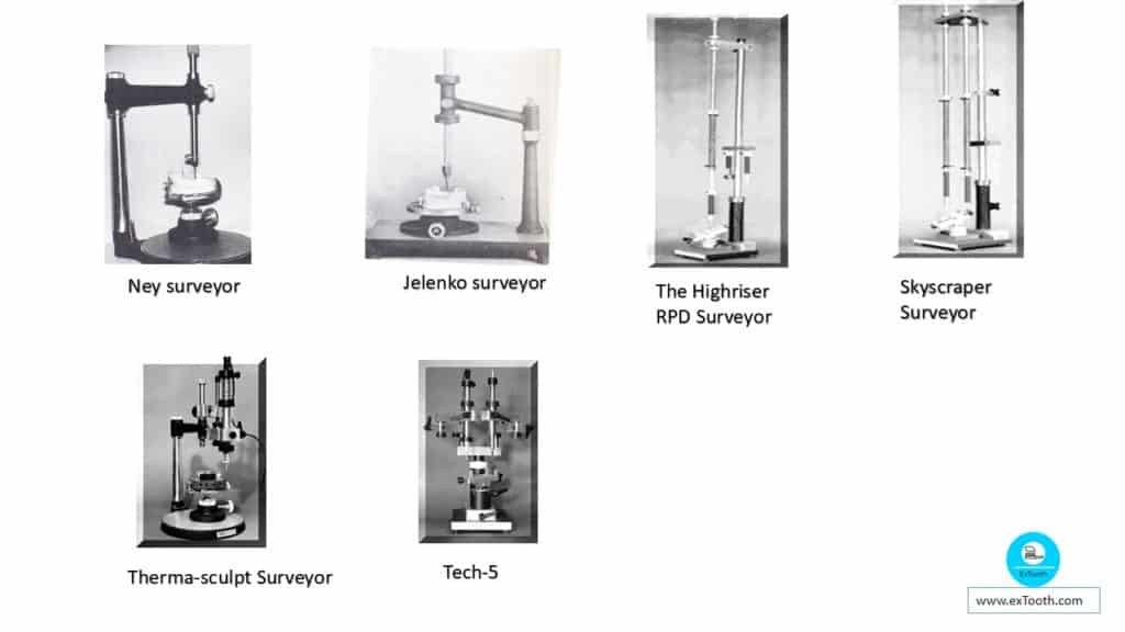
Types of dental surveyor
1. Ney surveyor
- The most widely used surveyors.
- Are precision-made instruments.
- The jointed horizontal member of the Ney is set.
- The principal parts of the Ney surveyor:
1. Platform on which base is moved
2. Vertical arm that supports superstructure
3. Horizontal arm from which surveying tool suspends
4. Table to which the cast is attached
5. Base on which the table swivels
6. Paralleling tool or guideline marker
7. Mandrel for holding special tools
2. Jelenko surveyor
The main components of the Jelenko surveyor are basically the same as those for the Ney surveyor except that by releasing the nut at the top of the vertical arm, the horizontal arm may be made to pivot.
3. William’s surveyor
The jointed horizontal arm of the Williams surveyor vary from both the Ney and Jelenko surveyors.This characteristic allows the vertical arm to be relocated to scribe the survey lines without relocating the cast.
4. The Highriser RPD Surveyor
Is a pendulum arm Block out/Survey Instrument.
The innovative design concept allows fluid movement;
The arm can easily turn back and forth, twist, or move up or down
Arm can be secured to maintain it at a set vertical height.
Spring tension is easily adjusted to individual preference.
Heating element attachment is created for simple use, and various size tips are available.
A lead holding chuck accepts a full four-inch lead instead of the customary short pieces.
5. The Skyscraper Surveyor
It is a dual pendulum Electronic Block out / Survey Instrument.
The dual-arm system has several advantages;
-The heating element need not be removed when surveying;
-By simply rotating the column, the modern tool is available for use.
6. The Therma-sculpt Surveyor Attachment
- It is an electronically heated arbor that can be easily to Ney-Jelenko type surveyor.
- The design concept enables the technician to produce
- wax sculpting businesses: from block out of RPD,
- attachment and implant procedures.
- Capabilities:
- Constant temperature control allows faster, consistent and predictable results
- sculpt the wax, not just melt it
- It takes only seconds to install or remove
- Eliminates the need for bunsen burner or alcohol torching of block-out tool
7. The Tech-5
The TECH-5 is a dual articulated arm RPD instrument.
One arm is dedicated to the electronic block out, a heated arbor that maintains precisely controlled temperature.
Heated arbor can be raised, lowered, or rotated effortlessly.
Other arm is doing the surveying functions and procedures.
It has a unique push-button chuck to advance (extend) the carbon marker.
Undercut gauges and carbon markers are easily interchanged.
Both the heating and surveying tubes have a true friction adjustment knob.
Both arms can move freely or be locked in place
Attachments used with the surveyor
Analyzing rod
This metal rod is set upon the teeth and ridges during the initial review of the cast to recognize undercut zones and to define the parallelism of surfaces without listing the cast.
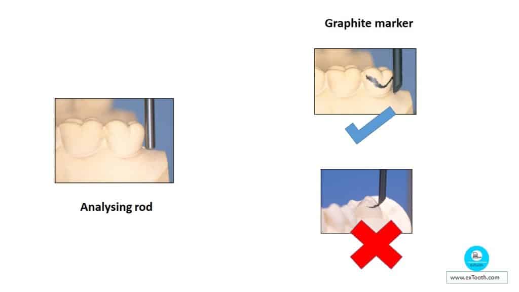
Graphite marker
It is moved around the tooth and along the alveolar ridge to identify and mark the position of maximum convexity (survey line) separating non-undercut from undercut areas. When surveying a tooth, the tip of the marker should be level with the gingival margin allowing the side of the marker to create the survey line.
A false survey line will be displayed if the tip of the marker is wrongly positioned.If this incorrect line is used in planning an RPD, faults will appear in the positioning of components, especially clasps.
Undercut gauge
Allows correct positioning of retentive clasp arms.
• Other, more sophisticated types of undercut gauge,
a) Dial gauges and
b) Electronic gauges.
• These attachments fulfill the same function as the simpler type of gauge.
Trimming knife
It is used to eliminate unwanted undercuts on the master cast. Wax is joined to these undesired undercut areas and then the surplus is eliminated with the trimmer so that the modified surfaces are parallel to the chosen path of insertion.When removal of undercuts is needed on a cast that is not to be replicated, a material such as zinc phosphate cement, which can hold the boiling out mode, is used. The dental surveyor is used to shape the cement before it is fully set. It can also be used to prepare guide surfaces on wax patterns of crowns for abutment teeth
SURVEYING
Principles of surveying
- To study the relative parallelism or lack of parallelism of the teeth and associated structures.
- To choose a path of placing a restoration that will meet the least tooth or tissue interference.
- To determine guiding plane surfaces to direct investment and relocation of the restoration as well as to reach the best appearance possible.
SURVEY LINE
The importance of locating retainer arms in the correct relationship to undercuts on abutments has been recognized in dentistry since 1916 when Prothers advanced the cone theory which divided molars and premolars into occlusal and cervical cones. In 1918, Fortunati pointed out that a mechanical device could be used for charting correct clasp outlines and Applegate reported that first commercial dental surveyor was designed by Weinsten’s and Roth in 1921. Roach considered survey lines from an anatomic perspective and described the survey lines of different teeth according to the long axis of the individual tooth. Ellot also described contours in relation to the long axis.
Definition
The line marked on the abutment tooth of the cast which indicates the greatest circumference of that tooth in that horizontal plane.
Types of survey line
According to Blatterfein
Diagonal; (Atypical-A)
High survey line;
Medium;
Low;
According to Ney
Class I; Runs diagonally from low position on the side of the rest to a high position on other proximal side.
Class II; Runs diagonally from high position on the side of the rest to a low position on other proximal side.
Class III; Same as high survey line.
According to kennedy: Height of contour
According to Cummer: Guide lines
According to Devan:
-Supra bulge
-Infra bulge
NEY SYSTEM:
Basic survey lines are classified as
- Class I survey lines
- Class II survey lines
- Class III survey lines
Class I survey lines:
Runs diagonally across the tooth surface, its situation relative to the intended rest position.
Class II survey line:
It runs diagonally across the tooth surface, but as mirror images of class I line. Clasp used here is gingivally approaching arm.
Class III survey line:
This type of survey lines runs parallel to the occlusal surface and lies just below it. Clasps used are of wrought, occcusally approaching arm with the terminal 2/3 rd of the arm entering the undercut.
BLATTER FEIN SYSTEM:
Blatterfein gave a comprehensive classification of survey lines, which is more practical in resolving clasping problems. He launched the terms Near Zones and Far Zone to separate the buccal and lingual tooth surfaces into 2 halves by a vertical line through the long axis of the tooth.
According to Blatterfein, survey lines are
- The medium survey line.
- The diagonal survey line.
- The high survey line.
- The low survey line.
The medium survey line:
- This line resembles the buccal or lingual surface of the tooth.
- This kind of survey lines regularly indicates the use of an occlusally approaching arm.
- The more resilient the arm in these cases the less the bracing effect, this makes its separate demand on bar length.
- A gingivally approaching arm may be used on a tooth having a medium survey line.
The diagonal survey line:
- These kinds of survey lines are present near the occlusal surfaces.
- Such lines are most commonly found on the buccal surface of canines and premolars
The high survey line:
- This survey line looks near to the occlusal than the gingival of the tooth in both near and far zones.
- These type of survey lines are found on the lingual surfaces of lower teeth and on bucaal surface and uppers.
The low survey line:
- This survey line is traced very low on the buccal or lingual aspect of a tooth.
- It usually happens as a result of marked inclination of the tooth, also found on the conically shaped tooth.
- The tooth surface with a low survey line can always bear a bracing arm and this may be of two kinds.
- A tooth surface producing a low survey line cannot carry a retentive clasp arm, because of insufficient undercut exist, and clasp arm placed in an undercut is situated near the gingival margin.
Importance of survey lines:
The survey lines divide that crown of the tooth into 2 zones
- An undercut area (everything below the line) and
- Non-undercut area (everything above the line) and this is called as suprabulge area and area below the line as infra bulge area. The significance of survey line is that any rigid, non-flexible part of the prosthesis must be designed to lie above the survey line and only flexible parts may be designed to go below it.
Based on type of survey lines
High Survey Lines
– Wrought wire clasp is generally preferred.
– Reverse back action clasp/ back action clasp is preferred in case of inclined tooth.
– Ring clasp is used on single standing molar teeth.
Medium survey lines
· Occlusally approaching clasp are indicted depending on the bracing effect cobalt chromium, cast gold or wrought wire can be used.
· Gingivally approaching arm may be used.
Diagonal survey line
Ring clasp is the most useful form of clasp, which enables the retentive arm to enter the undercut area from the far zone.
Low survey line
Reverse back action clasp or ring clasp can be provided.
Survey lines and Path of insertion are interdependent and by tilting of the cast in any direction both survey lines and path of insertion will change. Undercuts present for one path of insertion may be eliminated entirely for another path of insertion. If path of insertion are chosen without the use of dental surveyor, finished appliance may not go-to place in patients mouth become of interference an if forced to place at the expense of periodontium causes irreparable damage to the supporting tissues and have a poor chance to be in harmony with the masticatory organ.
It also determines the extent of blockout to be done for easy insertion and removal of the appliance and for the removal of refractory cast.
GUIDE PLANES
Two or more parallel axial surfaces of abutment teeth so shaped so as to direct prosthesis during placement and removal.
Functions of guiding planes
1. To produce a single path of placement and removal of the restoration.
2. To assure the intended actions of reciprocal, stabilizing and retentive components i.e. to produce retention against dislodgement of the restoration when the dislodging force is directed other than parallel to the path of removal and also to provide stabilization against horizontal rotation of the denture.
3. To eliminate gross food taps between abutment teeth and components of the denture.
Features of guide plane
1. Guiding plane surfaces should be such that they are as nearly parallel to the long axes of abutment teeth as possible.
2. It should be established on several abutments preferably more than 2 teeth.
3. It should be located at widely separated positions in the dental arch, which provides for more effective use of these surfaces. The effectiveness enhanced if these surfaces lie in more than one common axial surfaces of abutment.
4. As a rule of thumb: proximal guiding plane covers should be about 2/3 rd as full as the gap between the tips of adjacent buccal and lingual cusps or about one-third the buccolingual width of the tooth and should reach vertically about 2/3 the length of enamel crown portion of tooth form the marginal ridge vertically.
5. A guiding plane should generally be located on the abutment surface adjacent to an edentulous area. However excess torquing is inevitable if guiding planes squarely facing each other on alone standing abutment adjacent to an extension area is used.
6. Guiding plane surface should be like area on cylinderic object. It should be continuous surface unbounded by even ‘rounded’ line angles.
Functions of guide plane
1. Minimize the wedging stresses on the abutment teeth.
2. Make insertion and removal of the prosthesis easier for the patient.
3. Aid in stabilizing individual teeth.
4. Reduce the amount of blockout needed in areas of several undercut and thus minimize the amount of space between the denture and the tooth.
5. Contribute to the overall retention of the prosthesis
6. Ensures predictable clasp retention: it gives a positive direction to the movement of restoration to and from its terminal position.
Determination of the guiding plane
Tooth surfaces can be analyzed to determine this suitability as guiding plane surfaces and areas that are modified for this purpose can be noted. Guiding planes are the axial surfaces of teeth, which are contacted by the rigid elements of prosthesis as it is seated and removed from mouth. The surveyor can be used to locate existing or potential guiding plane surfaces so that it will assist in providing unimpeded passage of the appliance along the established path of insertion.
Guiding plane present on the abutment teeth then bound an edentulous space are well engineered guiding planes that are contacted by the stress arms of the framework and the prosthesis inserted and removed. So that the horizontal wedging virtually eliminated and all the transverse stresses transmitted to the tooth are effectively neutralized so that the whiplash effect is eliminated.
In contrast to this, creation of a flat distal surface on the abutment tooth next to an edentulous space has the effect of magnifying the stress which the denture base transmits to the abutment as base moves in function. Thus a pronounced guiding plane is not recommended for the abutment, which supports a distal extension. The interface between tooth surface and clasp should be such that a slight degree of movement of the base and the clasp is permitted without transmitting torsional stress to the tooth. Enough flattening of the distal surface of tooth should be accomplished to reduce the amount of undercut between minor connector and abutment but the interface should not be formed to make a glove like between the two surfaces.
Interferences
The prosthesis must be designed so that it may be inserted and removed without encountering tooth or soft tissue interference. Certain areas of the mouth – the teeth, soft tissue undercuts and bony exostosis – frequently interfere with the insertion of the partial denture. These areas have to be eliminated either by altering the tilt of the cast, or by surgery or on master cast by reasonable amount of blockout or by modifying interfering tooth surfaces.
Usually, interference that cannot be excluded for one reason or another will take priority over the factors of retention and guiding planes. These must then be modified with restorations that are in harmony with the path dictated by existing interference. In areas of interference can be eliminated then the axial contours of existing abutments may frequently be used with little alteration.
Interferences in the mandible
1. Tissues lingual to the remaining teeth that will be crossed by the major connector during insertion frequently causes problems. E.g. tori
2. The remaining teeth in the mandible, which are lingually inclined.
3. Areas lingual to the pear-shaped pad.
Lingually inclined teeth:
These unsupported or partially supported remaining premolar and molar teeth tends to drift in mesio lingual direction. Anterior teeth are not often involved in this drifting movement.
If the lingually inclined teeth are bilateral, the space available for lingually positioned major connector will be greatly reduced and results in encroachment of tongue space.
Major connector would have to be designed to stand well away from the lingual mucosa this results in
a. Tongue interference
b. Undesirable space where food and other debris would tend to collect
c. Unacceptable by the patient
Treatment options: Plan a labial bar major connector in place of a lingual one.
Disadvantages:
1. Poor patient acceptance because of bulk
2. Bulk causes uncomfortable and unattractive plumping of the lower lip
The most acceptable treatment option is either contouring the enamel of lingual surface or placing restorations on the teeth to eliminate the undercuts.
3. Areas lingual to the pear shaped pad:
This frequently causes interference to the path of insertion a lateral tilt of the cast on surveying table may help to eliminate some of the unilateral undercut in this area since it is the denture base that engages the undercut the acrylic resin can be retained to avoid the interference much easier, some resistance to lateral movement of the prosthesis will be sacrificed.
Interferences In Maxilla
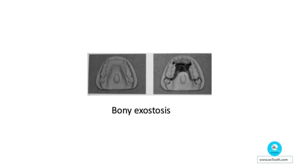
1. Torus Palatines, bony exostosis, undercuts buccal to the posterior edentulous ridge.
2. Buccally or facially tipped teeth with height of contour very close to the occlusal surface.
3. Anterior edentulous ridge in maxilla
1. Torus Palatines interferes with the placement of major connector and changing the tilt of the cast will not give the needed relief,
Treatment option: 1. Surgical intervention
2. Change of design
Bony exostosis or undercuts buccal to the posterior edentulous ridge are frequently encountered. Their surgical removal is not a complicated procedure and should be done to provide better support for denture base.
2. Buccally or facially tipped teeth: – These present with height of contour on the facial surface very close to the occlusal surface. This makes positioning of buccal clasp arms difficult for esthetic and mechanical reasons because of high clasp position undesirable tipping forces are created to mean the occlusal surface of the tooth which is much more damaging. If there buccally inclined teeth are located on one side of the arch only, tilting the dental surveyor table away from the teeth may lower, and the height of contour sufficient to permit the clasps to be located in a nearly ideal position.
If inclined teeth are located on both sides of the arch
– Tilting of cast is not helpful
– If tipping is not too secure, contouring the enamel surfaces to lower survey line may be done
– Full crowns restorations will be required to produce a height of contour for placement of clasp
3. An Anterior edentulous ridge:
This frequently presents an undercut situation. Giving cast a slight posterior tilt can control most of these undercuts. This not only helps in reducing the undercut but also places the anterior artificial teeth in a more natural position.
Modifying also controls this anterior undercut or eliminating the anterior flange of denture based butting the replacement teeth directly against the edentulous ridge to produce an esthetic result.
Areas of interference often overlooked are the distal line angles of premolar abutment teeth and the mesial line angles of molar abutments. These areas frequently offer interference to the origin of the circumferential clasp.
When such undercut exists three alternatives may be considered:-
1. They may be blocked out the same as any other areas of interference.
Disadvantage: least satisfactory because the origin of the clasp must then stand away form the tooth in proportion to the amount of blockout used and it is objectionable to the tongue and cheek and may create food trap.
2. Use of bar clasp if other contraindications to the use of bar clasp are not present such as severe tissue undercut or retentive areas that is too high on the tooth.
3. They may be eliminated by reducing the tooth contour during mouth preparation so that circumferential clasp can be used.
Orientation of the cast
For purposes of description, it is convenient to select a standard cast orientation when describing attachment, placement of clasps and connectors.
The standard position is for all casts to be considered as lower casts.
The position for description is from cast, behind the cast or from the position of the tongue.
All references to the right side of the cast apply thus to the right side of the cast from this position; for instance, on mandibular casts the right side would be the actual right side of the lower arch.
For maxillary casts, the right side, when describing it on the surveyor, would be the maxillary left quadrant. This is important when describing the tilt of a particular cast.
If a clasp is described as being low on a given tooth, it means that the clasp is toward the gingiva, regardless of whether it is a mandibular or a maxillary cast.
The standardized position minimizes confusion when placement of a clasp is described as being high or low. For instance, high on a maxillary cast might mean toward the gingiva, whereas high on the mandibular cast might be toward occlusal surfaces.
To further standardize, casts are oriented so that the anterior teeth are always toward the vertical member of the dental surveyor and away from the person making the survey.
Cast tilting:
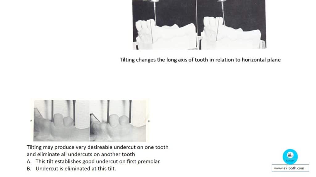
Tilting is merely adjusting the position of the cast, which thus changes the long axis of each tooth on the cast relative to the horizontal plane. Clearly, adjusting the tilt also will alter the state of the survey line in relation to the horizontal plane. More importantly, a change in tilt then changes the location and extent of any undercut area of the tooth.
Tilting is done to achieve the most favorable path of insertion. Tilting may be applied to improve desirable undercuts and to reduce unwanted undercuts. Through tilting, it is likely to increase the undercuts on one side of the tooth while decreasing them on the other side of the tooth. Thus it is essential to remember that when tilting one must examine the effect of any tilt to establish a more desirable undercut on other teeth involved in the design.
Although a given tilt may produce a very desirable undercut on one tooth, it may eliminate a popular undercut on the opposite side of the arch. Tilting can also be used to deal with possible undercuts to provide more uniform retention throughout the available abutment teeth. Tilting is also used to form a path of insertion that will allow the most productive use of an anterior space for replacement. It should be remembered that if a cast does not have good undercuts, tilting in itself will not produce them.
Basic cast tilts;
The primary site or tilt of the cast on the dental surveyor should be the horizontal tilt or, a zero tilt. In the horizontal inclination, occlusal surfaces of the teeth are at or near parallelism to the horizontal plane. This is the standard reference position from which further tilts originate.
The four necessary tilts from the horizontal, or reference positions, (1) The anterior tilt; anterior teeth are tilted downward.
(2) The posterior tilt; posterior portion of the cast is tilted down.
(3) The right lateral tilt; right portion of the cast is tilted down.
(4) The left lateral tilt; left portion of the cast is tilted down.
Tripoding:

Once a tilt has been chosen for a provided removable partial denture design, this angle should be maintained, so that it can be restored perfectly. This procedure is termed tripoding.
The most common method is to place the cast on the survey table at the desired tilt and, lowering the spindle of the dental surveyor with the analyzing rod in position, move the cast till three broadly separated spots on the anatomical part of the cast can be involved. This must be made with the analyzing rod at one vertical height.
Cast may also be tripoded by making vertical marks on cast. Anterior mark, Right posterior mark, Left posterior mark.
Undercuts:
Undercuts are classified as; a) Tooth undercuts or
b) Soft tissue undercuts.
May also be classified as; a) Favorable undercuts or
b) Unfavorable undercuts.
Since the removable partial denture is constructed of acrylic resin and cast metal which are non-rigid, it is important to locate the undercuts on the cast so that rigid portions of the prosthesis will be kept clear of them. Soft tissue undercuts frequently affect the design of the removable partial denture, particularly when considering the use of the infra-bulge, or bar-type, clasp. Soft tissue undercuts also can affect the base of the removable partial denture.
Types of block out;
1. Parallel block-out;
Proximal tooth surfaces are used as guiding planes beneath all minor connectors.
Tissue undercuts to be crossed by rigid connectors & by origin of bar clasps
Material; Hard baseplate wax or blockout material
2. Shaped blockout;
Done on buccal and lingual surfaces to locate plastic or wax patterns for clasp arms.
Material; Hard base-plate wax
3. Arbitrary blockout;
It is done on all gingival crevices, gross tissue undercuts situated below areas involved in design of denture framework & tissue undercuts distal to cast framework.
Labial and buccal tooth and tissue undercuts are not involved in denture design.
Material; Hard baseplate wax or oil-base clay
4. Relief;
Done beneath lingual bar connectors or the bar portion of linguoplates when indicated.
Areas in which major connectors will reach thin tissue, such as hard areas so frequently found on lingual or mandibular ridges and elevated palatal raphes.
Beneath framework extensions onto ridge areas for addition of resin bases.
Sticky wax sealed to cast-should be broader than major connector to be set on it.
Material; – Hard base-plate wax.
Colour code:
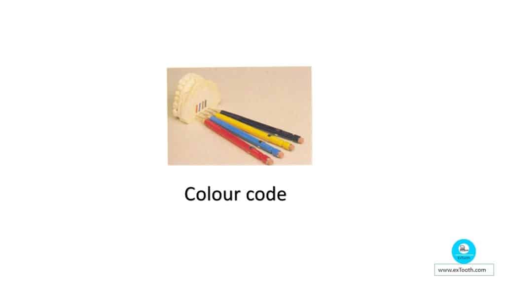
1. Red-areas to be ground, prepared, or recontoured
2. Blue-acrylic resin denture base
3. Brown-metal (framework or denture base)
4. Black-survey line and tissue undercut areas.
In surveying it is necessary to explain the following terms: Guide surfaces.
Path of insertion.
Path of displacement.
Guide surfaces (or guide planes);
• Two or more parallel axial surfaces on abutment teeth which can be adapted to restrict the path of insertion and enhance the stability of a removable prosthesis.
• Guide surfaces may happen naturally on teeth but more usually need to be prepared.
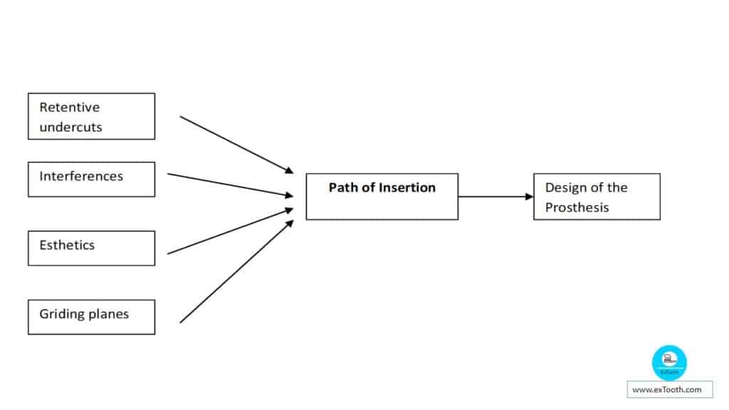
Path of insertion:
The path pursued by the denture from its initial contact with the teeth until it is fully seated. This path corresponds with the path of withdrawal and may or may not correspond with the path of displacement. There may be a unique path or many paths of insertion.
A single path of insertion may be performed if enough guide surfaces are contacted by the denture; It is most suitable to exist when bounded edentulous areas are present.
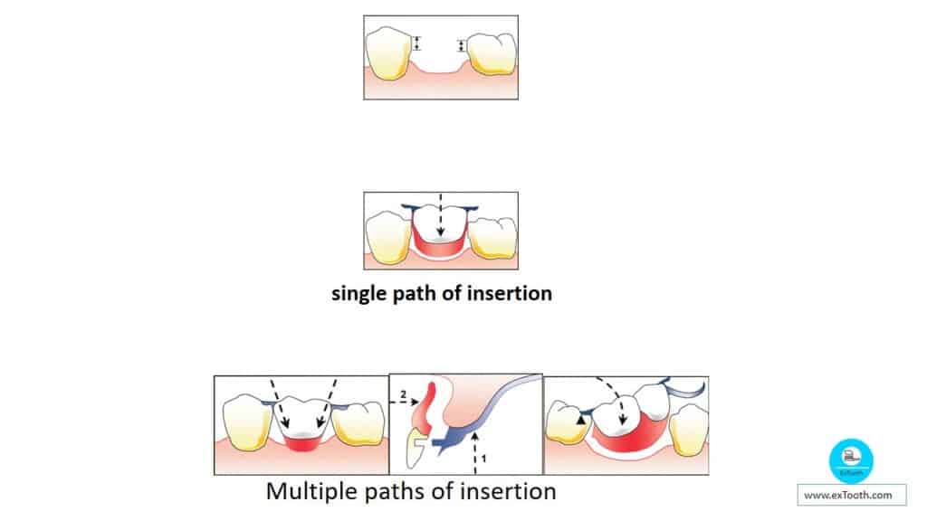
Multiple paths of insertion will exist where guide surfaces are not employed, like where the abutment teeth are divergent. Infrequently a rotational way of insertion can be used.
Path of displacement
This is the way in which the denture tends to be displaced in function. The path is variable but is believed for the purpose of design to be at right angles to the occlusal plane.
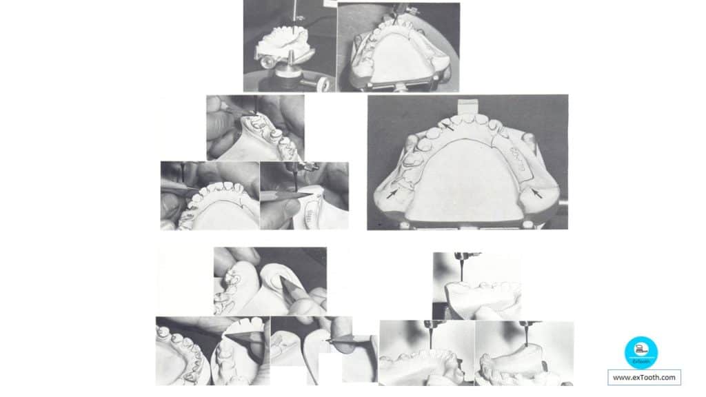
Surveying procedure;
This may be divided into the following distinct phases:
- Preliminary visual assessment of the study cast.
- Initial survey.
- Analysis.
- Final survey.
Anterior tilt (‘heels up’) Posterior tilt (‘heels down’).
A. Preliminary visual assessment of the study cast;
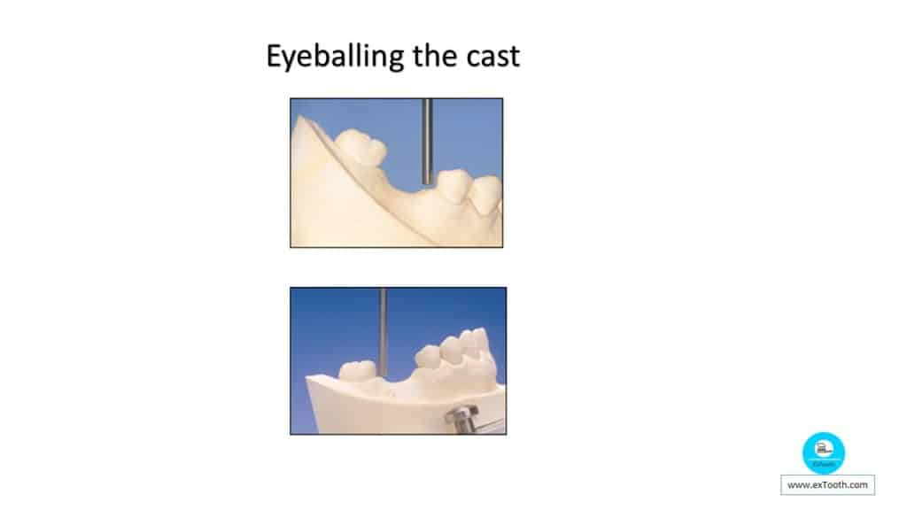
This frame has been described as ‘eyeballing’ the cast and is a useful preliminary, to the surveying procedure proper. The cast is kept in the hand and examined from above. The general form and arrangement of the teeth and ridge can be seen, any apparent problems noted and an idea taken as to whether or not a tilted survey should be applied.
Clinical practice shows that these are the positions of the cast that usually give the most crucial benefit. Nevertheless, a lateral tilt of the cast to right or left may also be indicated at the moment.
B. Initial survey
The cast is placed with the occlusal plane horizontal. The teeth and ridges are then surveyed to know undercut areas that might be employed to give retention in relation to the most suitable path of displacement.The location of the survey lines and the fluctuations in the horizontal range of undercut correlated with them should be recorded.
The number of the undercut can be ruled roughly from the size of the ‘triangle of light’ joining the marker and the cervical part of the tooth, or operated more accurately by utilizing an undercut gauge. An evaluation can then be made as to whether the horizontal extent of undercut is sufficient for retention purposes.
C. Analysis
- An RPD can be created on a cast which has been surveyed with the occlusal plane horizontal (i.e. so that the path of placement equals the path of displacement).Still, there are times when tilting of the cast is indicated so that the paths of insertion and displacement vary. Before deciding if the cast should be turned for the final survey the graphite marker in the dental surveyor is changed for an analyzing rod so that various positions of the cast can be examined without marking the teeth. Following aspects, in last survey with the cast tilted, are considered:
- Appearance.
- Interference.
- Retention.
i. Appearance; When a maxillary cast, including an anterior edentulous area is surveyed, it will usually be seen that there are undercuts on the mesial aspects of the abutment teeth. If the RPD is created with this vertical path of insertion there will be an unsightly gap between the denture saddle and the abutment teeth gingival to the contact point. This repulsive gap can be bypassed by presenting the cast a posterior (heels down) tilt so that the analyzing rod is parallel with the mesio-labial surface of the abutment tooth.

ii. Interference;
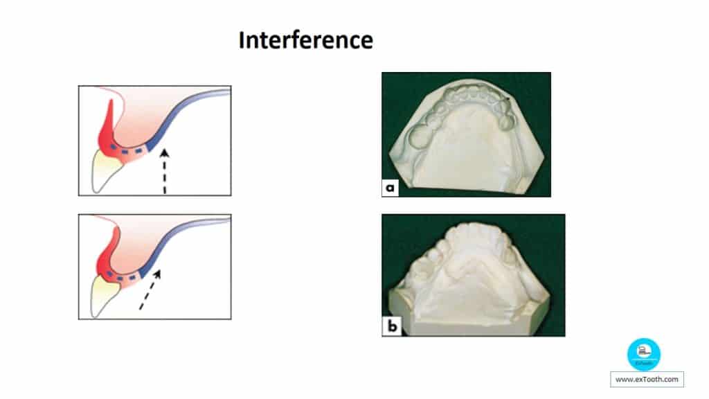
If the cast is given a posterior tilt so that the rod, and thus the path of insertion, is parallel to the labial surface of the ridge it is possible to insert a flange that fits the ridge accurately well as a poor appearance. Lingually tilted premolars can make it impossible to place a sublingual, or lingual bar connector sufficiently close to the lingual mucosa. Giving the cast an anterior (heels up) tilt avoids this interference. If interference from a tooth is present and cannot be avoided by selecting an appropriate path of insertion, consideration should be given to the possibility of tooth preparation, for example by crowning to reduce the lingual overhang.
iii. Retention; To obtain retention, undercuts must be present on teeth relative to the horizontal survey. It is a misconception to believe that changing the tilt of the cast will produce retentive undercuts if none exist when the cast is horizontal.
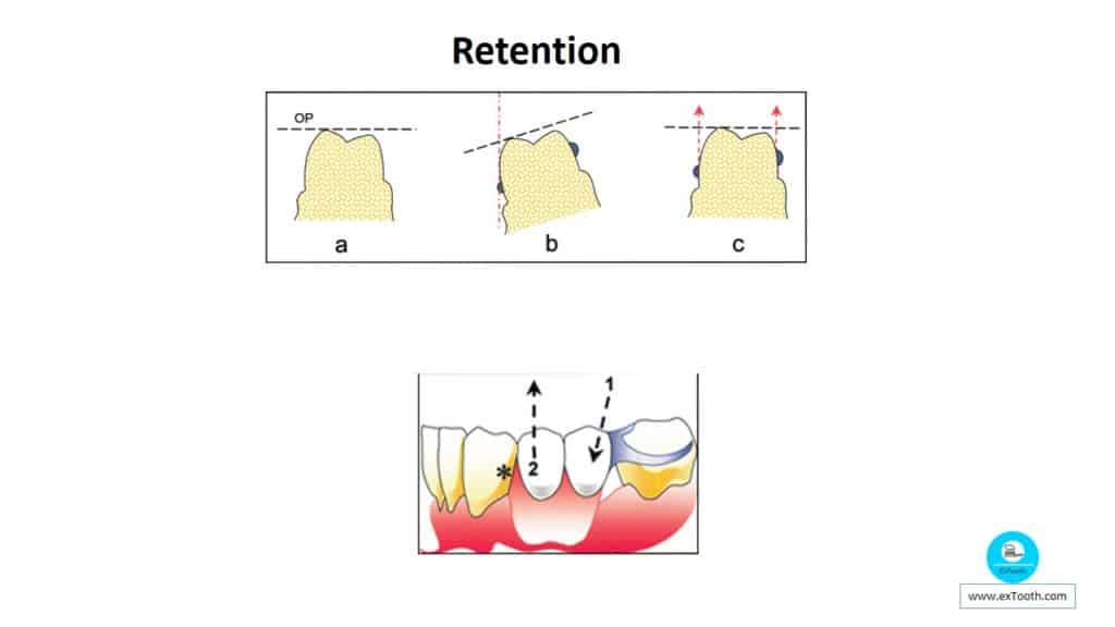
a) No undercuts on the tooth when the occlusal plane (OP) is horizontal.
b) An apparent undercut created by tilting the cast laterally.
c) Clasp arms placed in this false undercut do not provide any resistance to movement along the path of displacement.
The principle of tilting the cast to enhance retention is that by so altering the path of insertion,
(1)A rigid part of the denture can enter an area of the tooth surface or an area of the ridge which is undercut relative to the path of displacement (2). In this example, providing retention by engaging the distal undercut (*) of the canine may well look more pleasing than a clasp arm on the same tooth
iv. Final Survey; If it is decided that the cast should be tilted, the analyzing rod is exchanged for a marker different in color from that used in the first survey, and the final survey is carried out. It will then usually be found that the teeth to be clasped have two separate survey lines which cross each other. The former can be achieved by the use of guide surfaces or clasps while the latter is provided by clasps alone.
Alternatively, the analyzing rod is placed against one side of the base of the cast and a line drawn on the cast parallel to the rod. This is repeated on the other side and at the back of the cast so that there are three widely spaced lines parallel to the path of insertion.
Tilt transfer:
Examine the designed diagnostic cast and master casts for acceptability. Remount the diagnostic casts on the surveying table by aligning the tripod marks. Choose new tripod marks that can be touched by the stylus when it is locked in one position. The new marks should be easily located on the master cast. Place three widely separated marks on the diagnostic casts. Mark three spots on the master cast in exactly the same place as on the diagnostic casts.
Tripod the master cast using these three marks Since tripod marks are the same on both casts, the master cast will be tripoded in the same plane as the diagnostic cast. Two planes parallel to the same plane are parallel to each other.
VARIOUS TYPES OF DENTAL SURVEYOR USED IN DENTISTRY
Broken-Arm Dental Surveyor:
The basic difference between the surveyor and the broken arm surveyor is that it has got broken arm or hinged horizontal arm which is added to the basic surveyor. It has got many advantages such as it facilitates surveying and it allows surveyor to function as a milling machine through the adaptation of a straight hand piece to the surveying arm.
Examples of broken arm type of surveyors are
The Fort broken-arm dental surveyor.
Horrey surveyor.
Lentz broken arm dental surveyor.
The victor stoll dental surveyor.
The Williams gold refining company broken arm surveyor.
Nesor broken arm dental surveyor.
Ticonium company’s broken arm dental surveyor with a spring loaded surveying arm.
The Bego Paraflex surveyor has a solid horizontal arm and a parameter dial undercut depth gauge3.
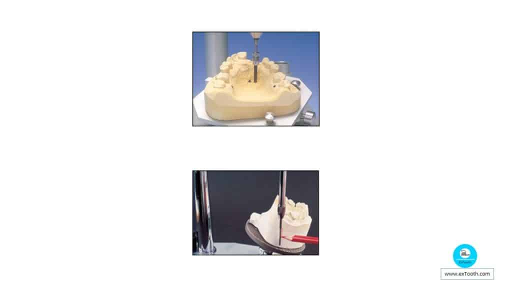
Milling Machine:
– Dental surveyor has been developed to function as milling machines or drill presses.
– These ensure the parallelism of guiding planes milled into casting.
Milling Machine:
Examples:
– Chayes milling machine.
– Austenal precision milling machine.
– Galloni Lso parallelometer with a cross-table, a finely made precision milling machine.
– Kavo precision dental milling mahine.
– The Frey and paralleling drilling machine for seita and Haag with magnetic table.
– Bachman parallelometer swingable/ movable magnetic table.
– Fah parallelometer with cross table.
– Alberct linear motar milling machine with built in motar and cross-table3.
Blockout Instruments:
The surveyor has proven indispensable during the laboratory task of blocking out undercuts on a master cast before fabrication of removable partial denture framework using a pendulum surveyor was a novel approach.
Features:
The device had a surveying arm at least 3 feet long that could pivot at some predetermined pint well above the cast holder. Hence the operators could move the surveying arm laterally, heat the attached waxing instrument in an open flame and then return the apparatus to the master cast and are used to shape and trim the blockout wax. As the angle of blockout is inversely proportional to the length of the surveying arm, the degree of blockout could be controlled by adjusting the arm length.
– Electrically heated blockout instrument have been in widespread for more than 40 years.
E.g.
Austenal surveyor:
It comes with a 42 inch long surveying arm. It is provided with an electrically heated waxing tool.
The Austenal view analyser:
It measures undercuts, a dial indicator show desired amount of undercut and flashing light signals when exact undercut is reached. The austenal flexseal preformed clasp patterns are used as a standard of measurement.
The paratherm surveying and blockout waxing instrument:
In this machine waxing tools will be heated electrically. The surveying arm move in 3 axes. Paratherm offers paraline, a non electrical survey or based on the paratherm design3.
Intraoral Surveyor
This is a device described for checking tooth preparations of abutment teeth for fixed or removable partial dentures. The device instantly and precisely shows the designed path of insertion of the prosthesis intraorally, it also serves as visual guide during preparation of teeth.Intra oral dental surveyor renders an economical, efficient and easily accessible method for allowing optimal tooth preparations for fixed and removable partial dentures
A simple intraoral dental surveyor using an acrylic resin base, a guide pin, a carriage and a paralleling tool can be made for determining the accuracy of tooth preparation in complex situation.
Surveying instruments of the intraoral dental surveyor can be made by
· Soldering a surveying rod to Allen wrench,
· Soldering a undercut gauge to Allen wrench,
· Rounding Allen wrench go lathe and
· Using small diameter Allen wrench as surveying instrument.
Recent Innovation
A recently designed dental surveyor exposes undercut areas by projecting a beam of laser light.
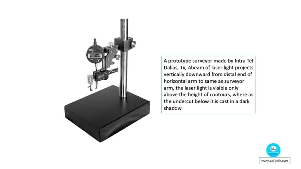
E.g. A prototype dental surveyor made by Intra Tel Dallas, Tx, Abeam of laser light projects vertically downward from distal end of horizontal arm to same as surveyor arm, the laser light is visible only above the height of contours, where as the undercut below it is cast in a dark shadow3
vreyro linomit
1 Jan 2021Thank you for sharing with us, I think this website really stands out : D.